Booting the board
After building the application binary, the next step is to use it to boot the board. The steps required by the boot procedure are described below.
This document shall use the hello_world sample as an example. The
detailed steps are, however, applicable to all samples or applications.
Warning
The boot procedure should be performed on your native OS. Using a virtualized environment is highly discouraged because of the potential USB-related issues that might appear.
Warning
If you’re using Docker or WSL2, you’re going to have to perform the steps presented below on your native OS.
Hardware setup
As described in The USB-C ports, the FRDM-IMX93 board has three USB-C ports, which we’ll be using to boot the board. Unless otherwise stated, the steps described below are applicable to both Linux and Windows users.
Connecting the DEBUG USB
First, connect the DEBUG USB port to your computer as shown in Figure 10.
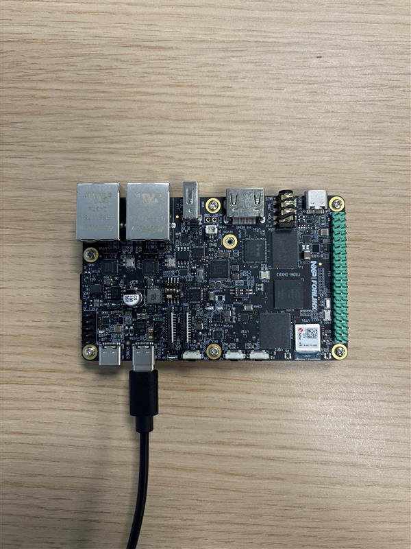
Figure 10 DEBUG USB connection
To check if your computer was able to detect the DEBUG USB, you’ll have to:
Run sudo dmesg. Afterwards, look for the following logs
(or something similar):
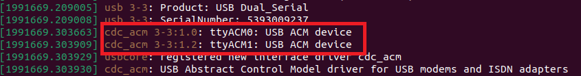
We are interested in the ttyACM0 and ttyACM1 serial devices.
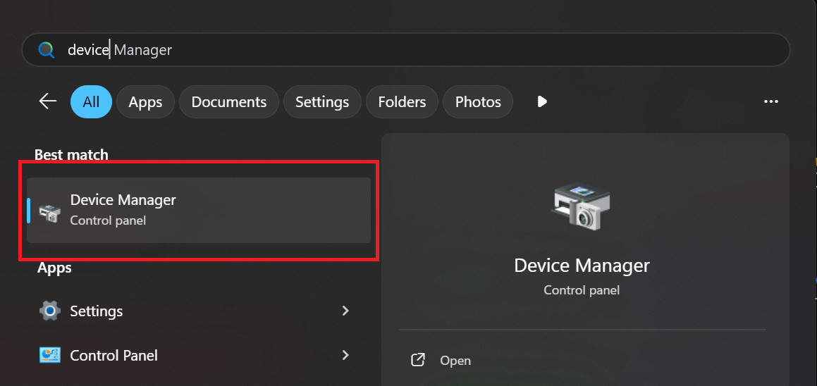
Open up
Device Manager:
Look for and open up the
Ports (COM & LPT)tab:
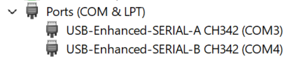
If the board was detected then you should see two new CH342 serial
devices. Note that their names might differ (i.e. they might not be
called COM3 and COM4)
Connecting the POWER USB
If everything went well, you should now connect the POWER USB as shown in Figure 11.
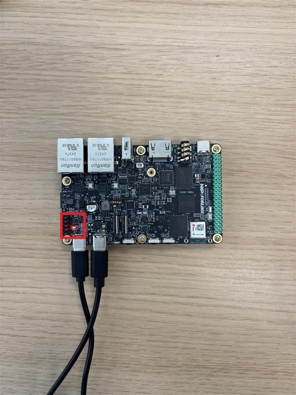
Figure 11 POWER USB connection
The red LED highlighted in Figure 11 indicates that the board is now connected to a power source.
Note
You may also connect the POWER USB to a USB-C phone charger.
Connecting the BOOT USB
Lastly, connect the BOOT USB as shown in Figure 12.
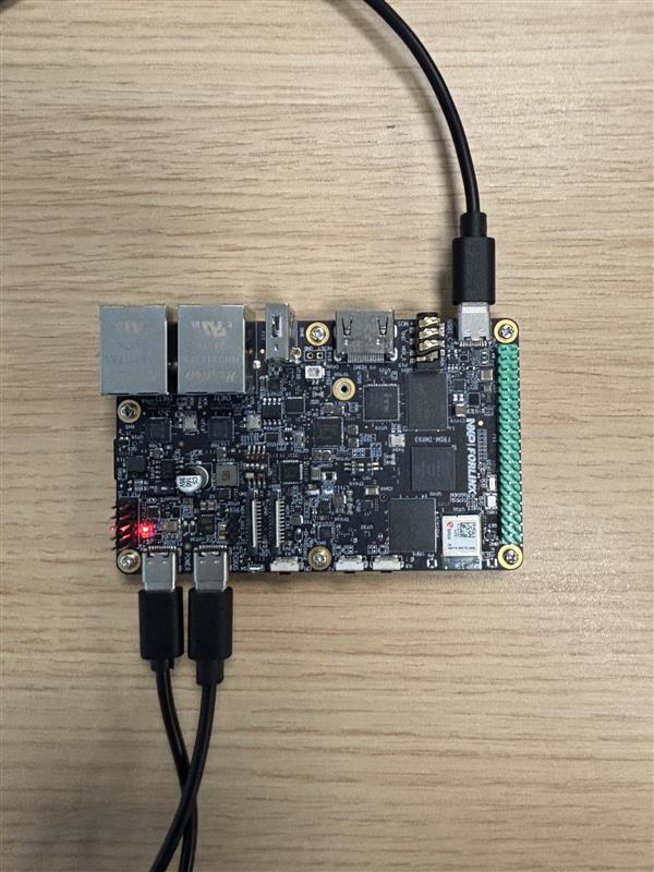
Figure 12 BOOT USB connection
To check if your computer was able to detect the BOOT USB, you’ll have to:
Note
Your computer won’t be able to detect the BOOT USB unless the board is powered on.
Run sudo dmesg. Afterwards, look for the following logs
(or something similar):

Make sure that the manufacturer is NXP. Additionally,
idVendor (VID) and idProduct (PID) should be 1FC9
and 014E, respectively.
Open up
Device Manager:
Look for and open up the
Human Interface Devicestab:
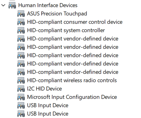
You should see that a new USB Input Device was added. To check
if the new entry was added by the board:
Open up the
Propertiestab by right-clicking on the device:
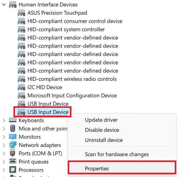
Go to the
Detailstab and select theHardware Idsproperty:
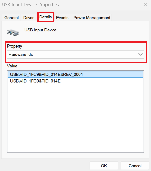
The device should have VID 1FC9 and PID 014E.
Serial console setup
The interaction between your computer and the application running on the FRDM-IMX93 board is performed via the DEBUG USB port. Therefore, if you wish to see the logs printed by your application during development, you’ll need to open up a serial console on your computer. To do so, you’ll have to:
Open a minicom console:
sudo minicom -D /dev/ttyACM0
Open up the
helpmenu by pressingCTRL-a Z: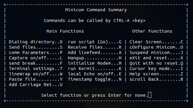
Open the
cOnfigure Minicommenu by pressingO(capital):
Open the
Serial port setupmenu by using the arrow andEnterkeys: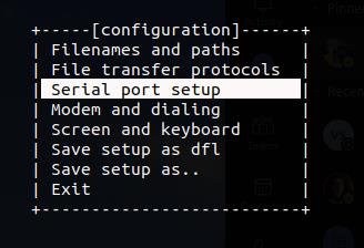
Make sure
Hardware Flow Controlis set toNo: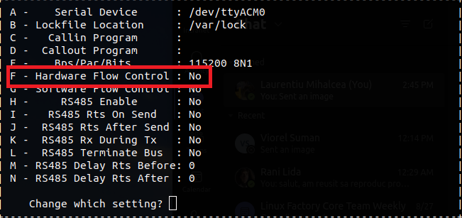
Make sure
Bps/Par/Bitsis set to115200 8N1: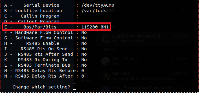
Close the
Serial port setupby pressingEnter.Navigate to
Save setup as dfland pressEnter.Navigate to
Exitand pressEnter.
You need to open a serial console for both of the serial devices
exported by the board (ttyACM0 and ttyACM1, respectively).
Therefore, you should end up with two active minicom sessions.
You only need to perform steps 2-9 once. To open the second minicom
console, just use the command described in step 1 (don’t forget to
change the name of the device if need be).
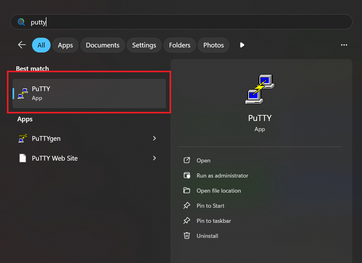
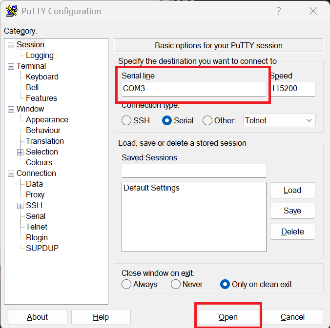
Open up
PuTTY:
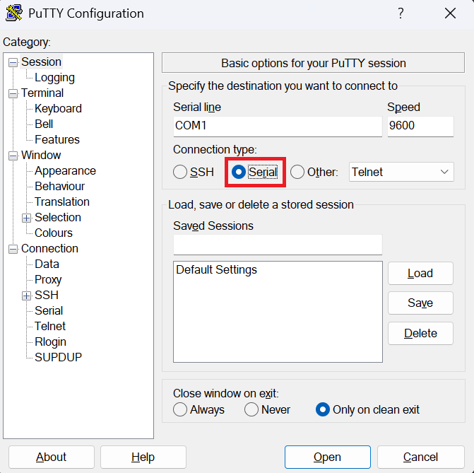
Select the
Serialconnection type:
Set the speed to
115200:
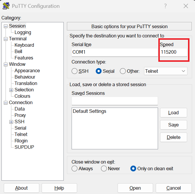
Type in the name of your serial device (line) and then click
Open:
You need to perform the steps described above for both of the serial devices exported by the board. Therefore, you should end up with two open serial consoles as shown in Figure 13.
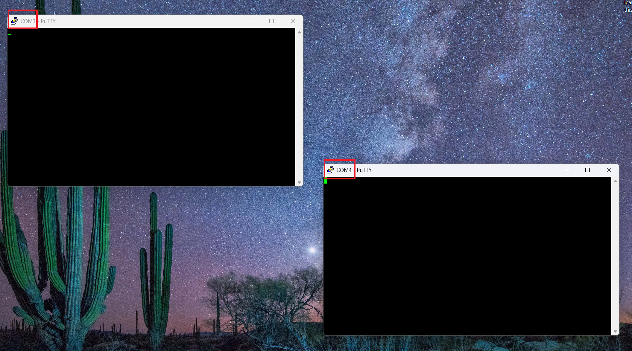
Figure 13 Windows PuTTY serial consoles.
As highlighted in Figure 13, the two serial
devices exported by the board are called COM3 and COM4 but,
in your case, this might differ.
You can find the name of your serial device (line) by following the validation steps described in Connecting the DEBUG USB.
Booting the board
As described in The boot switch, the board supports booting from multiple mediums. Consequently, before trying to boot the board, you’re going to have to select which medium to boot from. Table 1 shows all of the supported boot mediums and their associated boot switch states.
Warning
Before changing the state of the boot switch, you’ll have to power off the board. To do so, you can just disconnect the POWER USB.
You should NOT change the state of the boot switch while the board is powered on.
To avoid damaging the board’s POWER USB port, we encourage you to unplug it from your computer (instead of the board) or the power plug itself (if you’re using a USB-C charger).
USB boot
This mode requires you to have a physical connection with the board via
the BOOT USB port. Therefore, you’ll most likely end up using this
mode for quick prototyping. To boot from USB, first power off the board
and then put it into USB mode by changing the state of the boot switch
to 1000 (see Table 1). Afterwards, power on the board
and then run:
./boot/uuu -b ./boot/scripts/usb_boot ./boot/flash.bin ./build/zephyr/zephyr.bin
.\boot\uuu.exe -b .\boot\scripts\usb_boot .\boot\flash.bin .\build\zephyr\zephyr.bin
Note
The name of the uuu binary might differ from the one used above.
Therefore, make sure to adjust the command to suit your particular
use case.
If the board was successfully booted, you should see something similar to
Figure 14 in the terminal pane you’ve used to run
uuu.
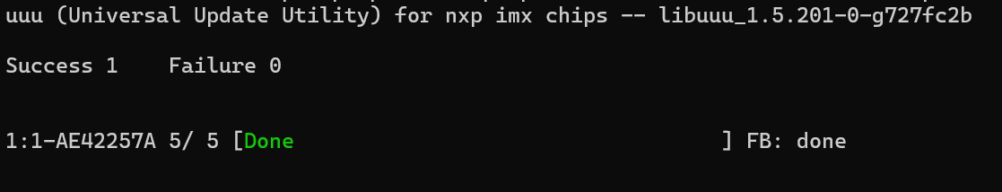
Figure 14 Boot success sample
Figure 15 shows the messages printed by the board during the boot process, which are captured on a Windows machine.
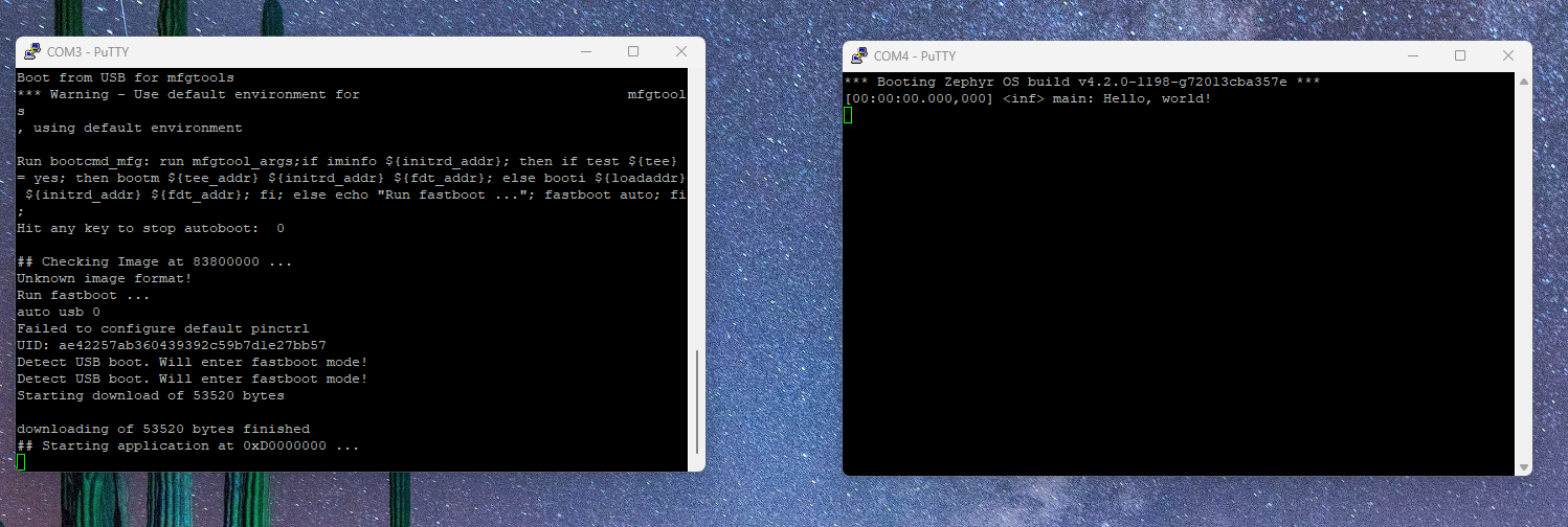
Figure 15 Logs printed during the board boot process (Windows)
The COM3 console shows the log printed by the bootloader, while the COM4
console show the log printed by the hello_world sample application.
The Linux equivalent of Figure 15 is depicted in Figure 16.
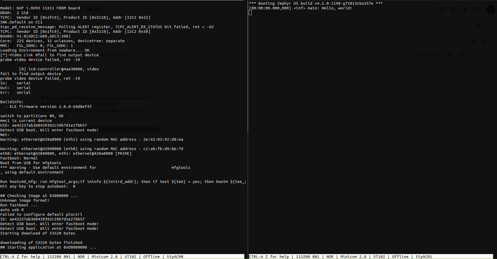
Figure 16 Logs printed during the board boot process (Linux)
The logs printed by the bootloader (via ttyACM0) as shown on the the
left side, while the logs printed by the application (via ttyACM1) are
shown on the right side.
SD card boot
As described in USB boot, the USB boot method works really well for quick prototyping/debugging since the application binary will change frequently. However, once this phase ends and the application binary is stable, you might need to store it somewhere on the board such that you won’t have to write it to the RAM each time the board is power cycled (i.e. turned off and then on). This is where the SD card boot method comes in handy.
To use this method, you’ll need a microSD card such as the one found here, which also comes with a microSD to SD adapter. If your computer doesn’t have an SD card port, you’ll also need to buy an USB SD card reader such as the one found here.
Once you have your SD card, you’re going to have to prepare it before actually using it. To do so [1]:
Insert the SD card in your computer.
Run
sudo dmesgand look for (logs may differ slightly):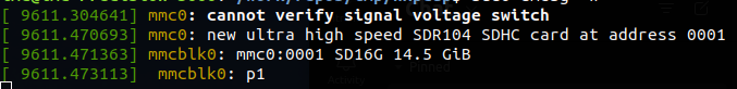
Identify the name of the SD card device. It should be something like
mmcblkx(xis a number):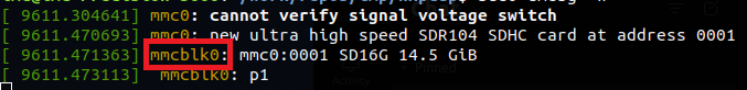
Run
fdisk:sudo fdisk /dev/mmcblk0 # replace with the name of your device
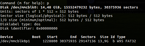
Press the following sequence of keys inside
fdisk:p [print currently existing partitions] d [press until all partitions are deleted] n [start the partition creation process] p [set as primary partition] 1 [set partition index to 1] 1228800 [set first sector offset] <enter> [press enter here] t [opens the partition type menu] 0b [select W95 FAT32 format] p [check if you have both of the partitions] w [write partition table and exit]
Your resulting partition table should look like this:
Format the partition as
ext4:# replace with your device name to which you append "p1" sudo mkfs -t ext4 /dev/mmcblk0p1
Mount the partition:
sudo mkdir -p /mnt/_tmp_nxp
sudo mount /dev/mmcblk0p1 /mnt/_tmp_nxp
Copy the application binary to the mounted partition:
sudo cp build/zephyr/zephyr.bin /mnt/_tmp_nxp
Unmount the partition:
sudo umount /mnt/_tmp_nxp
sudo rm -rf /mnt/_tmp_nxp
Remove the SD card from your computer
Insert the SD card in your computer.
Run
diskpartand switch to the newly opened terminal: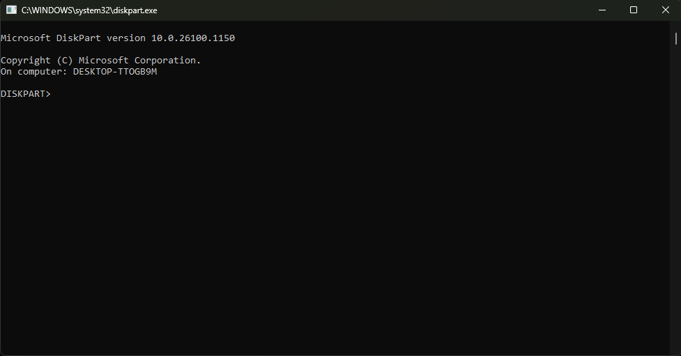
Note
On some setups, running the
diskpartcommand may require admin privilege. Therefore, if runningdiskpartresults in anAccess is deniederror message, try opening another PowerShell terminal with admin rights (see Changing PowerShell’s execution policy) and then running thediskutilcommand again.Run
list diskand identify the disk number corresponding to your SD card: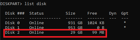
In the image above, the identified disk number is
2.Note
To identify the disk number you can look at the size of the disks and compare them with the size of your SD card. If this doesn’t work, you can unplug the SD card, run the
list diskcommand, plug in the SD card and run the command again. You can identify the disk number by checking which disk was added after the plug in operation.Warning
Make sure you identify the disk number correctly as the subsequent operations will erase all of the partitions on the disk.
Run
select disk <disk_number>(replacedisk_numberwith the number identified in the previous step):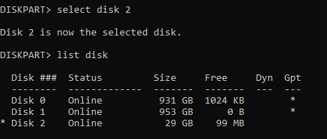
Note
If you run
list diskafter the select operation, you can see that an asterisk was added before the name of the selected disk. This can be observed in the figure above.Run
cleanto remove all of the partitions: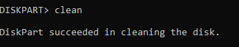
Run
create partition primary offset=10240 size=4096: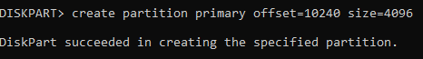
Note
If your SD card has less than 4GB, make sure to adjust the value passed to the
sizeargument. Generally, you can choose to omit it if the size of the SD card is <= ~32GB.Warning
Make sure your new partition has index (partition number) 1!
Run
format fs=fat32 label="NXPCUP" quick: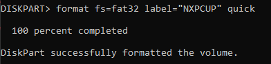
If everything went well, Windows will automatically mount your new partition. You can look for it by opening up
This PC: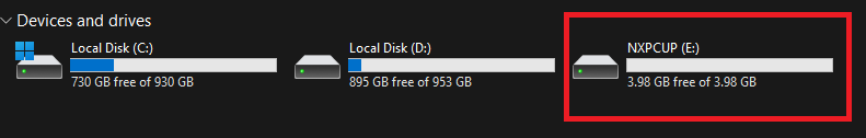
Close the
diskutilterminal and go back to thePowerShellterminal.Copy your application binary to the new partition:
# note: the drive letter may differ for you
cp .\build\zephyr\zephyr.bin E:\
Note
Alternatively, if you use the GUI, you can just drag and drop the application binary to the partition.
Remove the SD card from your computer.
After preparing the SD card, you can insert it into the SD card slot found on the bottom of the board. This is highlighted in Figure 17.
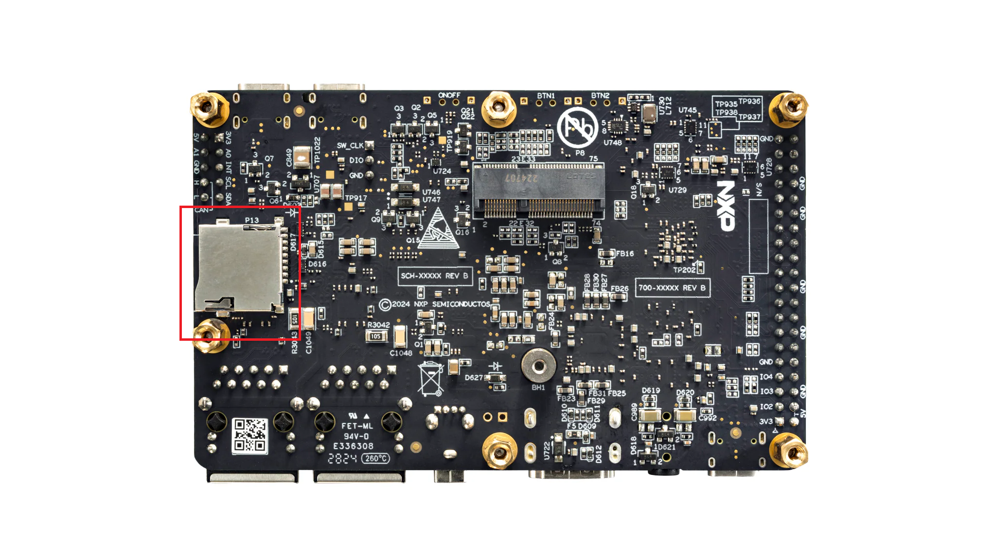
Figure 17 FRDM-IMX93 SD card slot
Before being able to boot the application binary, the bootloader needs to
be configured so that it will automatically load the application from the
previously created partition. To do so, put the board in USB mode by changing
the state of the boot switch to 1000 (see Table 1). After
doing so, power on the board by connecting the POWER USB port and then
run [2]:
./boot/uuu -b ./boot/scripts/sd_boot ./boot/flash.bin
.\boot\uuu.exe -b .\boot\scripts\sd_boot .\boot\flash.bin
If everything went well, you should see some output similar to that shown in Figure 18.
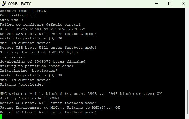
Figure 18 Sample output after running the sd_boot script.
The setup is now complete. Power off the board and then put it into SD
card mode by changing the state of the boot switch to 1100
(see Table 1). Now, when you power on the board again,
it should automatically start your application. As shown in Figure 19,
COM3/ttyACM0 will contain the bootloader logs, while COM4/ttyACM1
will contain the logs of your application.
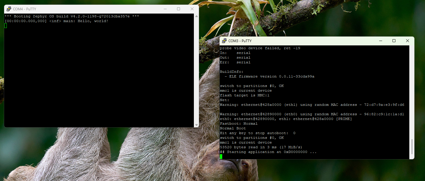
Figure 19 Booting the hello_world sample from the SD card.
To change the application binary:
Power off the board.
Remove the SD card from the board.
Insert the SD card into your computer.
Copy the new binary to the SD card as done during the SD card preparation.
Remove the SD card from your computer.
Insert the SD card into the board.
Power on the board.
Note
There’s no need to change the state of the boot switch while changing the application binary. Therefore, the boot switch should remain in the SD card mode while preforming all of the steps above.
eMMC boot
If buying an SD card or an USB SD card reader isn’t an option, you can make use of the 32GB eMMC integrated on the board. However, this will come with the cost of a slight increase in the complexity of the setup steps.
To boot from eMMC, you’ll first have to export the eMMC as an USB massive
storage device. You can think of this step as the equivalent of inserting
an SD card into your computer. To do so, first power off the board and put
it into USB mode by setting the state of the boot switch to 1000
(see Table 1). Afterwards, power on the board and then:
Run:
./boot/uuu -b spl ./boot/flash.bin
You should now see some output from the bootloader in the
ttyACM0serial console.Press
CTRL-Cinside thettyACM0console. You should now see theu-bootprompt as shown below: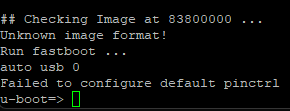
Inside the serial console, run:
ums mmc 0
Run:
.\boot\uuu.exe -b spl .\boot\flash.bin
You should now see some output from the bootloader in the
COM3serial console.Press
CTRL-Cinside theCOM3console. You should now see theu-bootprompt as shown below:
Inside the serial console, run:
ums mmc 0
After exporting the eMMC device, you’ll have to prepare it. To do so, please follow the SD card preparation steps described in SD card boot. Make sure you also copy the application binary to the eMMC device.
Once you’re done, go back to the serial console and type CTRL-C. You’ll
no longer see the eMMC device mounted in your filesystem. Finally, power off
and on the board without changing the state of the boot switch (i.e. board
should be in USB mode) and then run:
./boot/uuu -b ./boot/scripts/emmc_boot ./boot/flash.bin
.\boot\uuu.exe -b .\boot\scripts\emmc_boot .\boot\flash.bin
The setup is now complete. Power off the board and then put it into eMMC
mode by changing the state of the boot switch to 0100 (see Table 1).
Now, when you power on the board again, it should automatically start your
application. As shown in Figure 19, COM3/ttyACM0 will contain
the bootloader logs, while COM4/ttyACM will contain the logs of your
application.
To change the application binary:
Power off the board.
Switch the board to USB mode.
Power on the board.
Export the eMMC device as an USB massive storage device as shown in eMMC boot.
Copy the new binary to the eMMC device as done during the preparation step.
Power off the board.
Switch the board to eMMC mode.
Power on the board.