The L298N H-BRIDGE
Hardware setup
To simplify the block diagrams, the hardware setup has been split into three major steps, which are detailed below.
Connecting the data pins
The L298N H-BRIDGE module allows users to independently control the speed and direction of two motors at once. In this regard, each motor has three possible directions:
Forward: the motor is spinning forward.Backwards: the motor is spinning backwards.Fast stop/Brake: the motor is not spinning.
For a given motor, the direction is selected based on the logic level applied
to its corresponding IN pins:
IN1andIN2for motor 1.IN3andIN4for motor 2.
The relationship between a motor’s direction and the state of its corresponding
IN pins is summarized in Table 2.
Direction |
IN1/IN3 state |
IN2/IN4 state |
|---|---|---|
Fast stop |
LOW |
LOW |
Fast stop |
HIGH |
HIGH |
Forward |
HIGH |
LOW |
Backwards |
LOW |
HIGH |
To better understand the relationship between the two, some examples are presented below:
IN1is LOW,IN2is LOW => motor 1 is stoppedIN1is HIGH,IN2is LOW => motor 1 is spinning forwardIN3is HIGH,IN4is LOW => motor 2 is spinning forwardIN3is LOW,IN4is HIGH => motor 2 is spinning backwards
Note
The two motors are completely independent. For example, motor 1
could be spinning forward (via setting IN1 and IN2), while
motor 2 could be stopped or even spinning bacwards (via setting
IN3 and IN4).
The module also allows users to configure the speed of the motors by routing
two PWM signals through the ENA (for motor 1) and ENB (for motor 2)
pins. A 0% duty cycle PWM would result in no speed (i.e. motor is stopped),
while a 100% duty cycle PWM would result in the maximum speed.
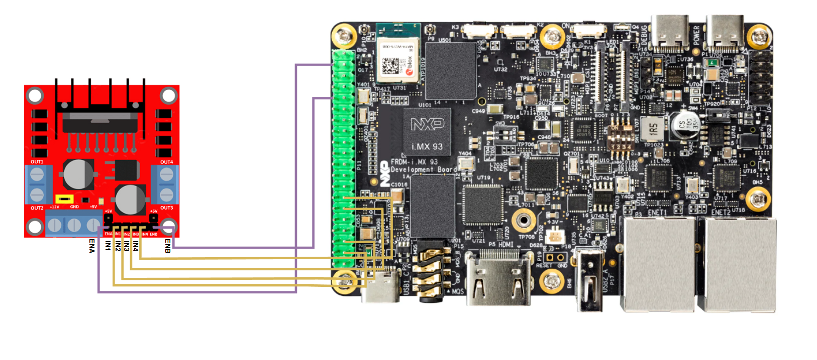
Based on Figure 4, we can use the following 6 pins
on the FRDM-IMX93 EXP GPIO header:
Pin 3 (
EXP_GPIO_IO02) for the IN1 GPIO.Pin 5 (
EXP_GPIO_IO03) for the IN2 GPIO.Pin 11 (
EXP_GPIO_IO17) for the IN3 GPIO.Pin 13 (
EXP_GPIO_IO27) for the IN4 GPIO.Pin 38 (
EXP_GPIO_IO20) for the ENA PWM.Pin 32 (
EXP_GPIO_IO12) for the ENB PWM.
Therefore, you should connect the pins on the two boards as indicated below:
L298N IN1 pin to FRDM-IMX93 pin 3.
L298N IN2 pin to FRDM-IMX93 pin 5.
L298N IN3 pin to FRDM-IMX93 pin 11.
L298N IN4 pin to FRDM-IMX93 pin 13.
L298N ENA pin to FRDM-IMX93 pin 38.
L298N ENB pin to FRDM-IMX93 pin 32.
Figure 31 highlights the aforementioned connections between the two boards.
Connecting the motors
The next step is to connect the two motors. The L298N module controls the attached motors via two pairs of pins:
OUT1andOUT2for motor 1.OUT3andOUT4for motor 2.
Figure 32 shows a potential way of connecting the two motors.
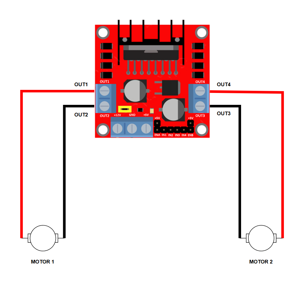
Figure 32 L298N motor connection diagram
Please be weary of how you choose to connect the motors as this will
impact the meaning of the Forward and Backwards directions.
For example, in the scenario shown in Figure 32,
applying the following states to the IN pins:
IN1HIGH,IN2LOWIN3HIGH,IN4LOW
would result in motor 1 spinning forward and motor 2 spinning backwards.
This is because the connections to the OUT pins for motor 2 were
inverted (comparted to motor 1 connections).
Despite this, the connection is valid and can be easily be handled in software (see the hbridge sample, which can handle this particular scenario).
Connecting the battery
The H-BRIDGE module and the development board need to be connected to the same battery. See Connecting the battery for more details.
Testing the connection
You can use the hbridge sample to check if the module was properly connected to the development board. Instructions on how to build and run the sample are provided in the How to build and the How to run sections.