The MG996R servo motor
Hardware setup
Before proceeding with the hardware setup, make sure that the FRDM-IMX93 board is powered off.
As per the MG996R datasheet, the servo motor has 3 signals that need to be connected:
The ground signal, which is known as
GND.The power signal, which is known as
Vcc.The PWM signal, which is known as
PWM.
Each of these signals uses a different color:
Brown for
GND.Red for
Vcc.Orange for
PWM.
Based on Figure 4, we can use the following 3 pins
on the FRDM-IMX93 EXP GPIO header:
Pin 39 (
GND) for the ground.Pin 2 (
VEXP_5V) for the power.Pin 7 (
EXP_GPIO_IO04) for the PWM.
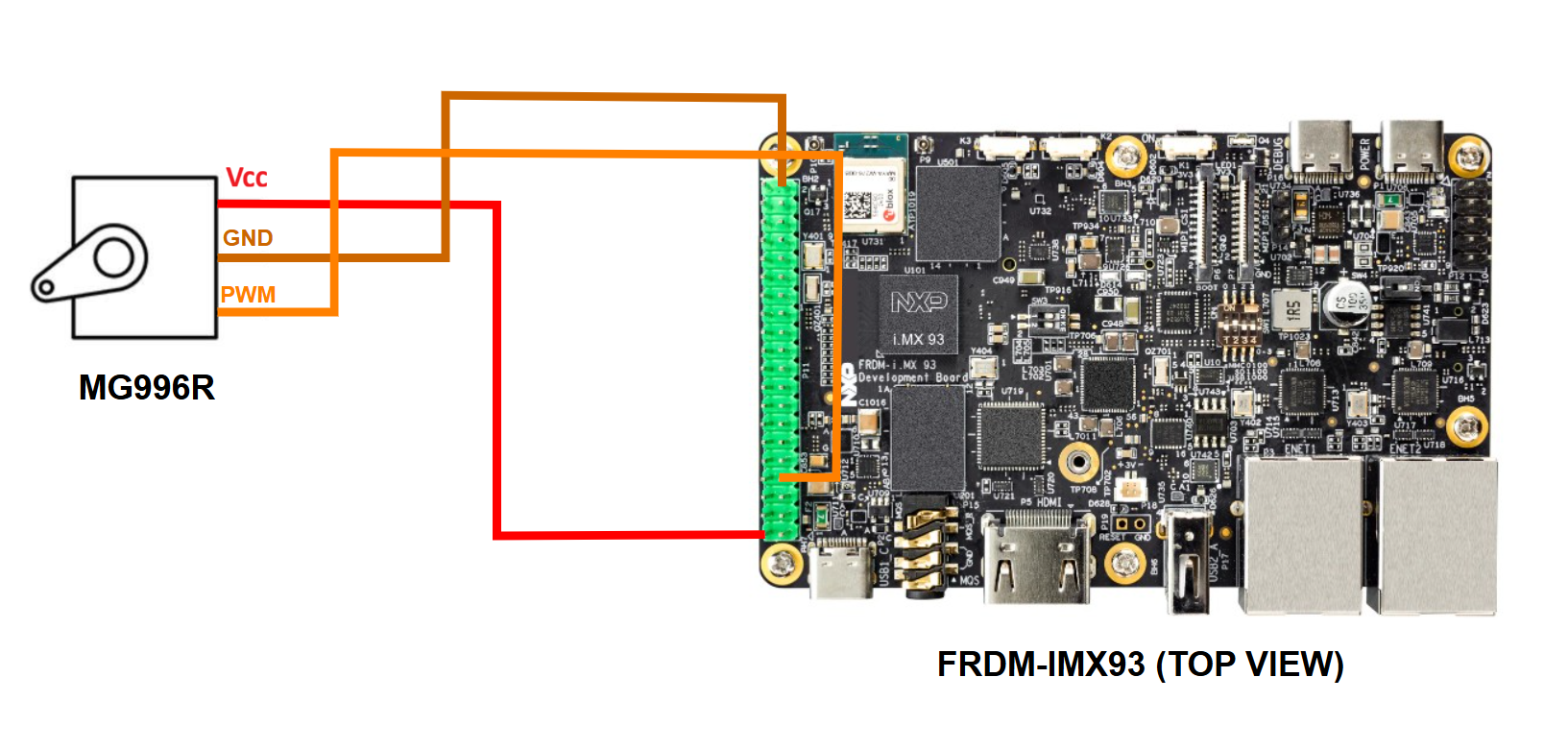
Therefore, you should connect the pins on the two boards as indicated below:
MG996R GND pin to FRDM-IMX93 pin 39.
MG996R Vcc pin to FRDM-IMX93 pin 2.
MG996R PWM pin to FRDM-IMX93 pin 7.
Figure 30 highlights the aforementioned connections between the FRDM-IMX93 board and the motor.
Additionally, the MG996R datasheet specifies the value of the PWM period, which should be set to 20 ms. The rotation angle is set by adjusting the duty cycle of the PWM signal, as described below:
1ms duty cycle corresponds to 0 degrees (leftmost position).
1.5ms duty cycle corresponds to 90 degrees (center position).
2ms duty cycle corresponds to 180 degrees (rightmost position).
Note
The range of the rotation angle detailed in the datasheet was shifted from [-90, 90] to [0, 180] here.
Testing the connection
You can use the servo sample to check if the servo motor was properly connected to the development board. Instructions on how to build and run the sample are provided in the How to build and the How to run sections.
Further reading
You may find further information on the servo motor in the datasheet.