Devicetree basics
What is a devicetree?
The devicetree is a tree-like data structure used by operating systems
such as Linux and Zephyr [1] to discover [2] and initialize the hardware
found on a system (e.g. FRDM-IMX93). In this format, the hardware devices
are represented as nodes, each of which having a set of properties.
Each devicetree node has exactly one parent and is a descendant of the
root node (known as /). Figure 43 provides
an example representation of a devicetree.
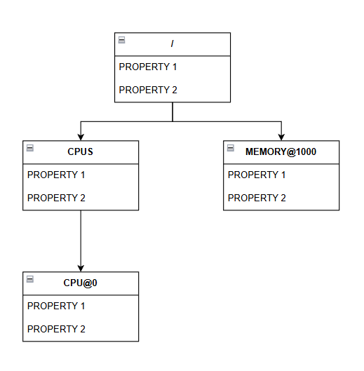
Figure 43 Devicetree example representation
In this particular example, the root node (/) has two children: CPUS
and MEMORY (ignore the bit after @ for now), representing a CPU cluster
(i.e. a set of CPU cores) and some memory. In turn, the CPUS node has a
single child: CPU (ignore the bit after @ for now), representing a single
CPU core. Based on this information, we can conclude that the system we’re dealing
with has a single CPU core and some memory.
Additionally, we can see that all nodes have a set of properties: PROPERTY 1 and PROPERTY 2, respectively that can be used to, for example, provide additional information about the underlying hardware. For example, you’ll most likely want to specify the size of the memory.
Although all nodes depicted in Figure 43 have the same properties, this is NOT a requirement. Usually, each node will have its own set of properties, which might differ from that of the other nodes.
The devicetree source and devicetree blob
Much like the compiled programming languages such as C, the devicetree has a textual representation known as the devicetree source (DTS), which is meant for us, humans. This means that you can read and write a DTS as you normally would with any other text file.
The textual representation of a devicetree is not really suited to be used by the OS, which is why the devicetree also has a binary representation, which is known as the devicetree blob (DTB) or flattened devicetree (FDT) [3]. The DTS is converted into its binary form via a process called compilation (similar to how you’d compile a C source file) by a tool known as the devicetree compiler (DTC). Figure 44 emphasizes the relationship between the three components. The DTC takes a devicetree source as input, compiles it, and produces a DTB, which can then be used by your OS.
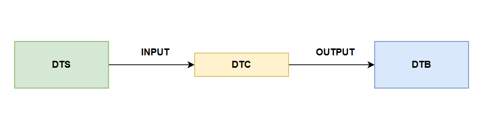
Figure 44 Relationship between the DTS, DTB, and DTC.
To identify a DTS file, you can look at its extension, which, in most cases,
will be .dts. On the other hand, devicetree blobs will usually end in
.dtb.
Writing a devicetree source file
As previously mentioned, the devicetree is a tree-like data structure, which is why the DTS file is made up of nodes defining hardware devices.
Devicetree nodes
The definition of a devicetree node is shown below:
node-name@unit-address {
   /* properties or other node definitions go here */
};
where:
node-name: name of the node. This is usually chosen such that it reflects the functionality of the underlying device (e.g. cpu, memory, adc, etc..) and should, ideally, be chosen from the list shown in the devicetree specification, section Generic Names Recommendation.@unit-address: this bit is optional and can be used to distinguish between devices with the same functionality (e.g. a machine may have 4 CPUs). Its meaning is relative to the bus the hardware device sits on. However, usually, theunit-addressbit will be set to the start of the device’s address space.
The name of the root devicetree node must be set to /. Thus, its
definition would be:
/ {
   /* properties or other node definitions go here */
};
Devicetree nodes defined within the context of other devicetree nodes form a child-parent relationship. For example:
/ {
   node-1 {
   };

   node-2 {
   };

   node-3 {
   };
};
node-1, node-2, and node-3 are all children of the root node.
Additionally, these tree nodes are placed on the same level.
With this in mind, we’d describe the hardware topology shown in Figure 43 as follows:
/* node properties were intentionally omitted */

/ {
  cpus {
    cpu@0 {
    };
  };

  memory@1000 {
  };
};
Devicetree node labels
A devicetree node may also contain a label. In such cases, the format of the node is:
node-label: node-name@unit-address {
   /* properties or other node definitions go here */
};
where:
node-label: name of the label to attach to said node. Needs to be unique.
After adding a label, you can then use the & operator, followed by the
name of the node label (i.e. &node-label), to reference the node inside
a property or a devicetree source file.
Some examples are presented below:
Referencing a node inside another node’s property:
my_amazing_label: my-node {
  /* properties or other node definitions go here */
};

my-other-node {
  my-property = <&my_amazing_label>;
};
Referencing a node defined in the DTSI:
/* content of my-example.dtsi */

some_label: my-node {
  status = "disabled";
};
/* content of my-example.dts */

/* include the nodes defined in my-example.dtsi */
#include "my-example.dtsi"

/* change "my-node"'s status from "disabled" to "okay"
&some_label {
  status = "okay";
};
Devicetree node properties
As mentioned earlier, each node can have a set of properties, thus allowing developers to provide additional information about the underlying hardware (e.g. the address space of a device). The format of a property is shown below:
my-node {
  <property_name> = <property_value>;
};
where:
property_name: name of the propertyproperty_value: value of the property
Below you may find a list of some of the most commonly used properties and their meanings.
The compatible property
Description
Used to describe the programming model for a given device. An operating system might use this property to, for example, choose the suitable device driver.
Format
The format of the property is shown below:
my-node {
  compatible = <stringlist>;
};
where:
stringlist: list of null terminated strings describing the programming model. For example:"fsl,aips-bus","fsl,aips-bus", etc..
Examples
Below you may find some example node definitions:
aips1: bus@30000000 {
  compatible = "fsl,aips-bus", "simple-bus";
  /* other properties were intentionally omitted */
};
gpio1: gpio@30200000 {
  compatible = "fsl,imx8mp-gpio", "fsl,imx35-gpio";
  /* other properties were intentionally omitted */
};
The status property
Description
Used to describe the operational status of the device.
Format
The format of the property is shown below:
my-node {
  status = <string>;
};
where:
string: null terminated string.
As per the devicetree specification, section 2.3.4, status, the value
of the status property may be one of (you’ll most likely end up working
with just the first two):
"okay": device is operational."disabled": device is not currently operational but may become in the future."reserved""fail""fail-sss"
Note
If a node doesn’t have the status property, it is assumed that the
device is operational (i.e. equivalent to status = "okay";).
Examples
Below you may find some example node definitions:
wdog3: watchdog@302a0000 {
  /* other properties were intentionally omitted */
  status = "disabled";
};
flexspi: spi@30bb0000 {
  /* other properties were intentionally omitted */
  status = "okay";
};
/* this node doesn't have the status property. This is equivalent
 * to explicitly having the status property set to "okay".
 */
usdhc3: mmc@30b60000 {
  /* other properties were intentionally omitted */
};
The #address-cells and #size-cells properties
Description
Used to specify the number of u32 cells that make up the
address and size fields in a child node’s reg property.
Consequently, this property is specified inside nodes that have children.
Format
The format of the property is shown below:
my-node {
  #address-cells = <u32>;
  #size-cells = <u32>;
};
where:
u32: unsigned 32-bit integer value
If missing, it is assumed that #address-cells is set to 2 and
#size-cells is set to 1.
Examples
Below you may find some example node definitions:
/* in this example, we expect the address and size fields of the
 * children to be made up of two 32-bit cells (i.e. both of them
 * will be 64-bit).
 */
my-parent {
  #address-cells = <2>;
  #size-cells = <2>;

  /* other properties were intentionally omitted */

  child-1 {
  };

  child-2 {
  };
};
/* in this example, we expect the address field to be made up of
 * two 32-bit cells (i.e. address will be 64-bit). The size field
 * will be made up of 1 32-bit cell (i.e. size will be 32-bit).
 */
my-parent {
  #address-cells = <2>;
  #size-cells = <1>;

  /* other properties were intentionally omitted */

  child-1 {
  };

  child-2 {
  };
};
The reg property
Description
Used to describe the address space of a device in the context of a bus.
Format
The format of the property is shown below:
my-node {
  reg = <prop-encoded-array>;
};
where:
prop-encoded-array: list of(address, size)pairs.
The address field is made up of N, u32 values, where N is
the value specified via the #address-cells property in the parent node.
The size field is made up of M, u32 values, where M is
the value specified via the #size-cells property in the parent node.
Examples
Below you may find some example node definitions:
/* assume that the parent has:
 *
 * #address-cells = <1>;
 * #size-cells = <1>;
 */
 my-child@3000 {
   /* the address space of this device starts from 0x3000 and
    * ends at 0x7000 (since the size is set to 0x4000 bytes)
    */
   reg = <0x3000 0x4000>;
 };

 my-child@50000000 {
   /* this device has two address spaces:
    *
    * 1) First spanning from 0x50000000 to 0x50001000
    * 2) Second spanning from 0x50001000 to 0x50002000
    */
   reg = <0x50000000 0x1000>, <0x50001000 0x1000>;
 };
/* assume that the parent has:
 *
 * #address-cells = <2>;
 * #size-cells = <2>;
 */
my-child@100000000 {
  /* the address space of this device starts from 0x100000000
   * (this address results from concatenating 0x1 and 0x0)
   * and ends at 0x100001000 (this size results from concatenating 0x0
   * and 0x1000)
   */
  reg = <0x1 0x0 0x0 0x1000>;
};
Note
If the reg property is present, you must specify the node’s
unit address in the node name (i.e. the bit after @).
The node’s unit address must match the starting address of the address space.
Devicetree source include files
When developing an application written in C, you may choose to add some of your function/structure/macro definitions inside a header file, which will allow you to use said definitions in multiple locations.
In the context of devicetrees, the equivalent of a header file is called a devicetree source include (DTSI), which is usually used to provide node definitions for an SoC. This file is then included in your board’s DTS.
To include a DTSI in your DTS, you can use the C preprocessor #include
directive as follows: #include <name_of_your_dtsi>.
Below, you may find an example DTSI called my-example.dtsi:
/* content of my-example.dtsi */
my-node-1 {
};

my-node-2 {
};

my-node-3 {
};
You can include the node definitions from my-example.dtsi by adding
a #include "my-example.dtsi" statement in the beginning of your DTS:
/* content of my-example.dts */

/* this pulls in the node definitions from my-example.dtsi */
#include "my-example.dtsi"

my-node-4 {
};

my-node-5 {
};
After preprocessing, this results in the following my-example.dts file:
my-node-1 {
};

my-node-2 {
};

my-node-3 {
};

my-node-4 {
};

my-node-5 {
};
Therefore, largely speaking, what the preprocessor does is it takes the node definitions from your DTSI and adds them to your DTS file.
Furthermore, you may have the same node definitions in your DTS and DTSI files. For example:
/* content of my-example.dtsi */

my-node {
  compatible = "v1,m1";
  /* this is a boolean property, which takes no value. Specifying its name is enough */
  my-amazing-property;
  status = "disabled";
};
/* content of my-example.dts */

#include "my-example.dtsi"

my-node {
  status = "okay";
};
As you can see, both the DTSI and DTS define the my-node node.
In this particular case, the preprocessor will merge the two node
definitions. If both of the nodes have the same property with different
values (e.g. status is set to disabled in the DTSI and set to okay
in the DTS), the resulting node will use the value set in the DTS
(e.g. in this case, my-node will have status set to okay).
Otherwise, the resulting node will use the properties from both node
definitions.
With this in mind, the resulting node will have the following definition:
/* content of preprocessed my-example.dts */

my-node {
  compatible = "v1,m1"; /* taken from the DTSI */
  my-amazing-property; /* taken from the DTSI */
  status = "okay"; /* taken from the DTS */
};
If the devicetree node defined in the DTSI has a label, you can use that instead of the node’s name. For example:
/* content of my-example.dtsi */

my_node_label: my-node {
  compatible = "v1,m1";
  my-amazing-property;
  status = "disabled";
};
/* content of my-example.dts */

#include "my-example.dtsi"

&my_node_label {
  status = "okay";
};
Devicetree overlays
Certain applications require certain node configurations. In such cases, you can customize the resulting DTB by applying a devicetree overlay to it.
Much like devicetree sources and blobs, devicetree overlays also have a textual representation known as devicetree source overlay (DTSO) and a binary representation known as devicetree blob overlay (DTBO). The DTC takes in a DTSO as input, compiles it, and produces an output DTBO. You can then apply (i.e. the OS or compiler reads your DTB and DTBO and then merges the content of the two) the DTBO to your DTB to modify the node definitions.
Let’s look at an example:
/* content of my-example.dts */

my-node-1 {
  compatible = "v1,m1";
  my-amazing-property;
};
/* content of my-example.dtso */
my-node-1 {
  compatible = "v2,m2";
};
In this particular case, after the my-example DTBO is applied to the
DTB, my-node-1 will have the following definition:
my-node-1 {
  compatible = "v2,m2";
  my-amazing-property;
};
When applying devicetree overlay, the nodes are merged using the same logic that’s employed for DTSIs and DTSs.
Further reading
For additional information, the reader is encouraged to also check out the devicetree specification.