The development board
The FRDM-IMX93 is a small and compact board provided by NXP, which is based on the i.MX93 chip and, thus, offers the following hardware features [1]:
2 x ARM Cortex-A55 cores
1 x ARM Cortex-M33 core
3 x USB-C ports
32GB eMMC
2GB of RAM
40-pin expansion header
The top view of the board is shown in Figure 1.

The USB-C ports
As previously mentioned, the FRDM board comes with three USB Type-C ports, which are highlighted in Figure 2.
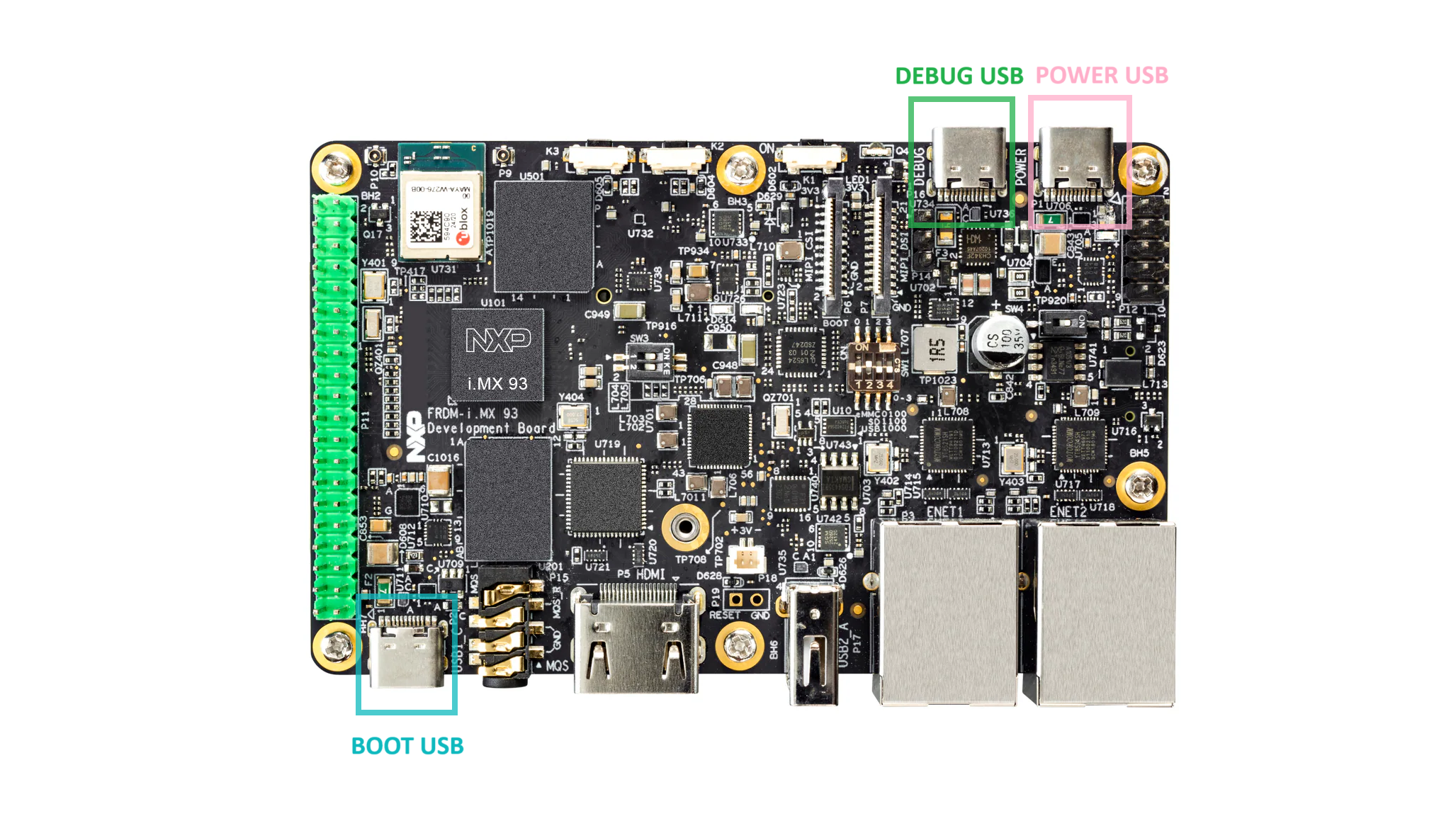
Figure 2 FRDM-IMX93 USB Type-C ports
Each of these ports serves a different purpose, as briefly described below:
BOOT USB (highlighted in cyan): used to boot the board.
DEBUG USB (highlighted in green): used for debugging the board and communicating with the bootloader.
POWER USB (highlighted in pink): used to power the board.
During development, you’ll most likely find yourself utilizing all three of them.
The boot switch
Before booting the board, you’ll need to tell the boot ROM where to get the bootloader from. To do so, you’ll have to mechanically change the state of a series of switches, colectively referred to as the boot switch. Its location is highlighted in Figure 3 using green.
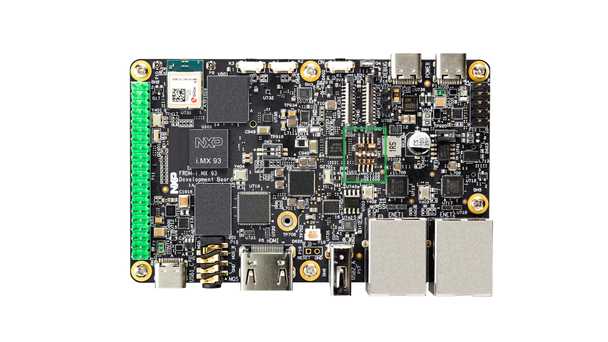
Figure 3 FRDM-IMX93 boot switch
As you can see, the boot switch is made up of four switches, numbered from 1 to 4, each of them having two possible states: ON or OFF. The boot medium is selected by placing these switches in the appropriate states.
As a convention, we’ll be referring to the state of the boot switch as a combination of four digits with the following format: abcd, where a is the state of switch 1, b is the state of switch 2 and so on. Each of the letters that make up the state of the boot switch has two possible values: 0 and 1, signifying that the switch is either OFF or ON. Some examples are presented below:
0000: all switches are OFF
1111: all switches are ON
1000: switch 1 is ON, switches 2-4 are OFF
1100: switches 1-2 are ON, switches 3-4 are OFF
1001: switch 1 and 4 are ON, switches 2-3 are OFF
With this in mind, Table 1 provides a list of the supported boot mediums and their associated boot switch states.
Boot switch state |
Boot medium |
|---|---|
1000 |
USB |
1100 |
SD |
0100 |
eMMC |
The expansion header
To allow communicating with external modules (e.g. I2C, SPI, etc.), the FRDM-IMX93 board is equipped with a pin header made up of 40 pins. This is referred to as the expansion header and is highlighted in Figure 4.
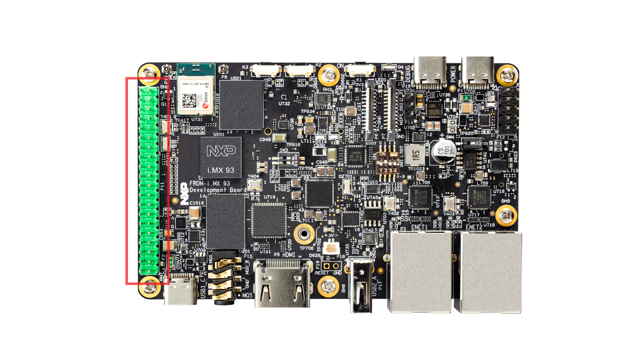
Figure 4 FRDM-IMX93 expansion header.
When assembling the car, you’ll be using this header to connect all of your components to the board.
The board schematic
Looking at just pictures of the board might not provide enough information to, for example, be able to properly connect an external component. Consequently, this is where the board schematic comes in handy. Among other things, the board schematic shows how the board components are connected together and which signals are routed through the board’s pin headers.
In this regard, NXP provides the schematic for the FRDM-IMX93 board, which can be downloaded from here [3]. Upon inspection, the downloaded archive contains three directories:
.
├── Design Files
├── Gerbers
└── PDF
You may find the board schematic under PDF/SPF-94611_B1. An excerpt from the
schematic showcasing the expansion header (taken from page 20) is presented in
Figure 5.
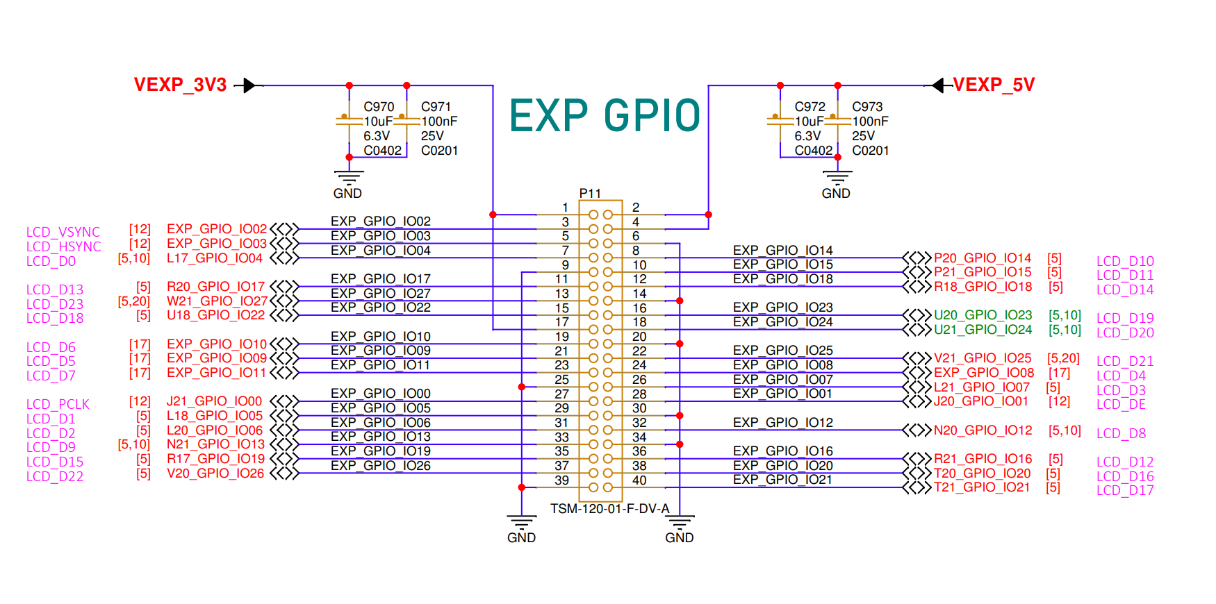
Figure 5 FRDM-IMX93 schematic excerpt showcasing the expansion header.
Upon taking closer look, we can extract the following information regarding the expansion header:
the part number/ID for the pin header is TSM-120-01-F-DV-A. Usually, you can use this identifier to search more information on the Internet regarding the component (for instance, the datasheet).
the unique identifier for the component is P11. This ID is usually used to distinguish between the different components of the board and is usually unique. You can also use this ID to find the component on the physical board (note that the ID is usually small and, since there’s a lot of components, the task of identifying where the ID is written on the PCB might not be trivial).
the name of the signals routed through this component. This is the most important piece of information because it will tell you how to connect your external component.
All of this information is also highlighted in Figure 6.
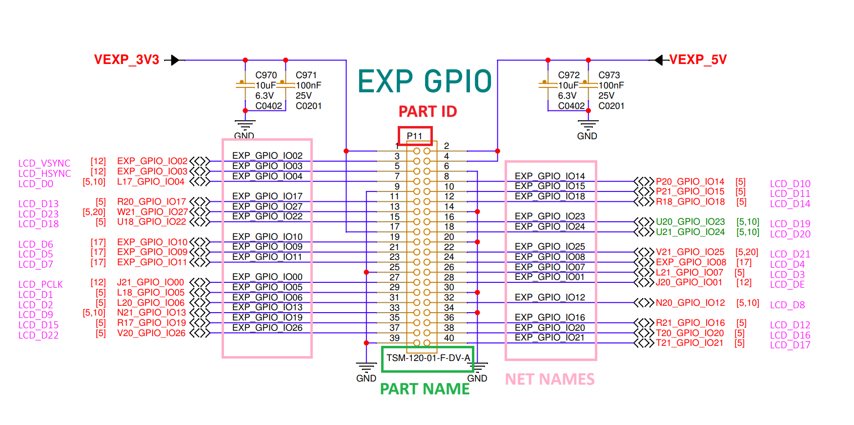
Figure 6 Highlighted information from EXP GPIO.
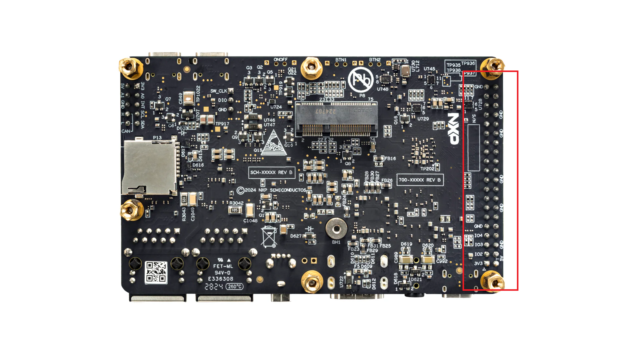
We can also see that the pins are numbered from 1 to 40. To find the pin numbers on the physical board, you’ll have to look at the labels inscribed on its back. The bottom view of the board is shown in Figure 7. The section of interest is highlighted in red.
Per the schematic shown in Figure 5, pin number 1 is tied to 3.3V. Consequently, the pin inscribed with the 3V3 symbol on the back of the board corresponds to pin 1. This is highlighted in Figure 8. Once pin 1 has been determined, we can also determine the position of the rest of the pins by looking at their positions relative to pin 1 on the pin header.
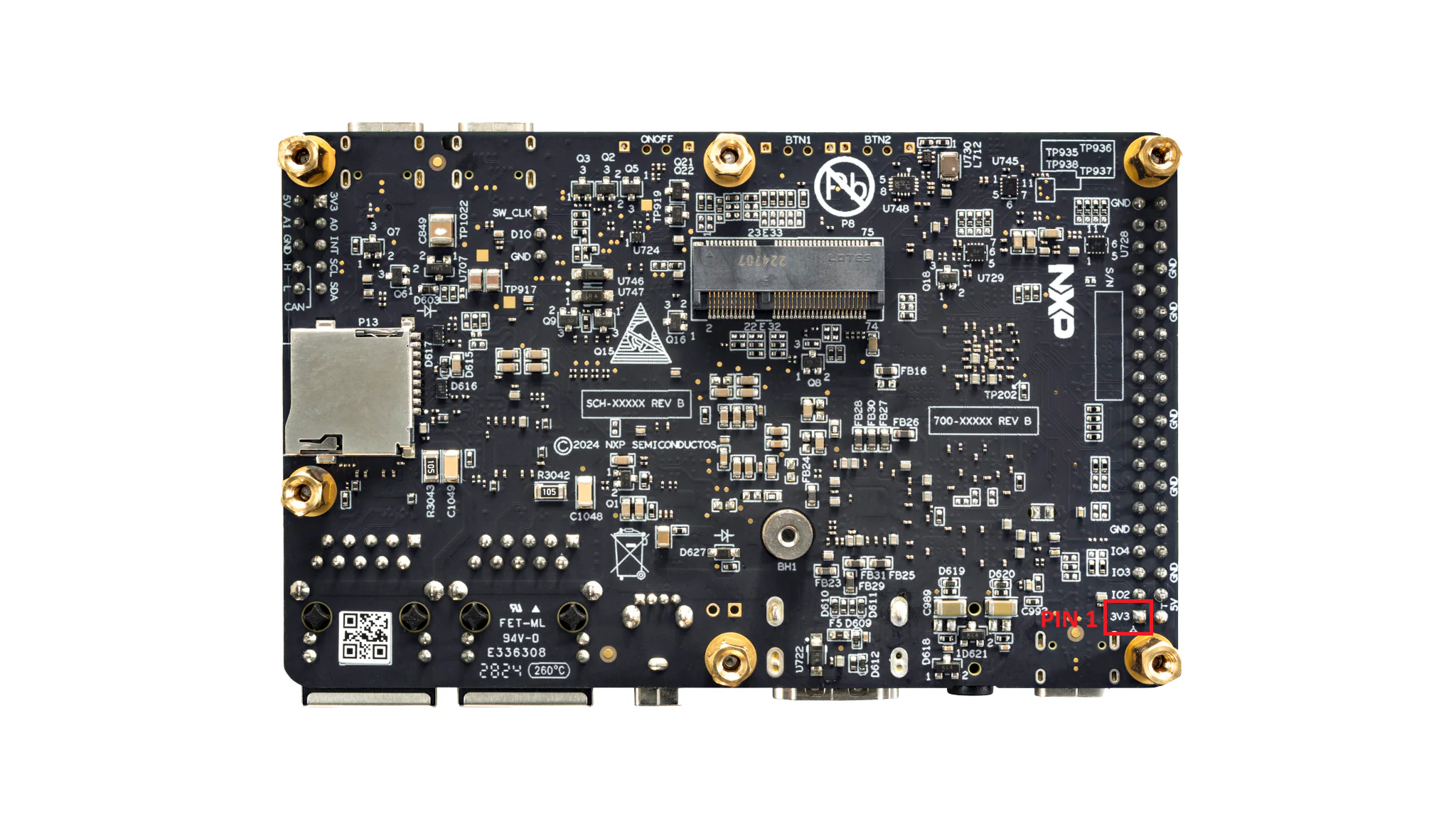
Figure 8 Finding pin 1 on the expansion header
Note
You can use any of the labels inscribed on the bottom of the board to find your reference pin.
The reference manual
Another piece of documentation you might find yourself needing while working with the FRDM-IMX93 is the SoC’s reference manual, which can be found here [5]. This provides information on the memory map and various IPs that make up the SoC. The information is neatly organized in chapters, each of which providing details on a certain IP or topic. Figure 9 provides an excerpt taken from the reference manual.
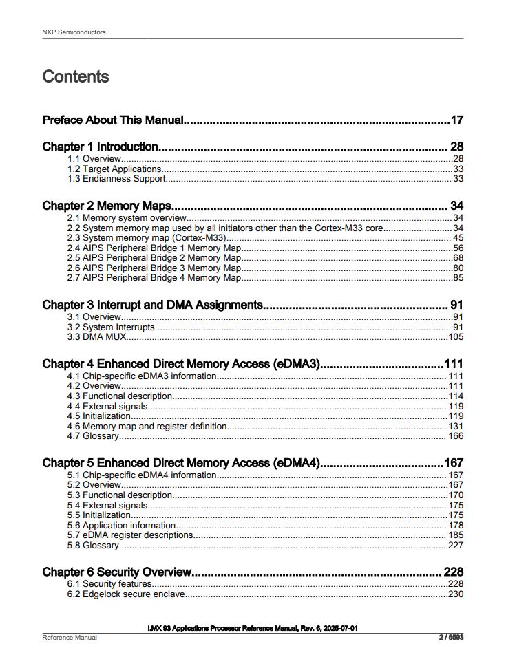
Figure 9 Excerpt taken from the i.MX93 reference manual
Additional resources
Generally, you’ll find all of the official board and SoC documentation on the FRDM-IMX93 and i.MX93 home pages in the Documentaton section.
Glossary
bootloader: piece of software that handles the hardware initialization and can be used to load other images (e.g: our application)
boot CPU: CPU that handles the boot process
boot ROM: first piece of software executed by the boot CPU when the board is first powered on.
PCB: stands for Printed Circuit Board and is used to refer to the FRDM board.
IP: stands for Intellectual Property and is used to refer to the hardware modules that make up the chip.